Pre Incorporation Multi Cavity Tooling Acceptance Standards
Pre-incorporation tooling acceptance demands strict metallurgical certification, cavity-decoupled Cpk metrics, and formal promoter novation agreements.


Title
Delaware corporate registrations, Singapore ACRA filings, and German Handelsregister entries share a severe commercial consequence when hardware founders cut steel before company incorporation. Individuals executing supplier contracts prior to formal certificate issuance shoulder personal legal liability under established corporate statutes, including Delaware General Corporation Law Section 106 and UK Companies Act Section 51. The promoter signs individually.
Tooling deposits create personal exposure. Injection tooling for multi-cavity parts represents a capital commitment ranging between thirty thousand and two hundred fifty thousand dollars. When a founding team signs an injection mold purchase contract while their entity remains unfiled, the individual signatories carry joint and several liability for progress billings, fabrication overruns, and canceled machining orders.
Toolmakers demand immediate cash deposits to purchase certified forged billets, hot runner manifolds, and specialized ejector assemblies. If the founding entity does not yet exist as a distinct legal person, title to that physical steel rests in contractual limbo. Tooling builders retain statutory artisan liens or mechanic liens over all tool blocks sitting in their facility until receipt of final disbursement.
A founder funding fifty percent of an offshore sixteen-cavity tool from personal savings often assumes that initial wire transfer secures ownership over the mold. Statutory reality differs. In the absence of an incorporated entity with registered signing authority, the vendor maintains physical custody and legal title under local commercial codes until complete clearance of all staged milestones.
Promoters executing fabrication contracts in personal capacities assume joint liabilities that survive legal registration unless explicitly novated by board resolution.
Vendor liens attach upon delivery. Cross-border toolmakers rarely alter their standard procurement agreements for unincorporated startups. Overseas fabrication facilities in Shenzhen, Taichung, or Monterrey draft sales quotations specifying that tooling remains the seller’s unencumbered property until the client issues final written production approval and clears all invoicing.
If founders encounter friction, run short of personal funds, or split their equity before official entity incorporation, the tooling shop freezes the mold. The shop reallocates machining center capacity to other commercial clients. Regaining control over half-cut cavity blocks requires expensive cross-border litigation under foreign jurisdictions where local courts favor registered domestic manufacturing entities over foreign individual citizens.

Promoter Exposure during Pre Registration Tooling Execution
Common law jurisdictions treat corporate promoters as direct contractual counterparties when agreements predate incorporation filings. When three founders commission an engineering firm to machine a complex thirty-two-cavity hot runner tool, each founder stands exposed to third-party claims if the downstream seed funding round collapses. Personal assets, bank balances, and intellectual property developed outside the corporate shell face judicial attachment during payment defaults.
Creditors enforce outstanding machine shop balances against the wealthiest individual promoter rather than dividing claims proportionally.
Mitigating promoter risk demands explicit conditional contracting structures before committing down payments. Protective purchase orders establish that vendor obligations run exclusively to the enterprise in formation, designating the signatories as interim custodians rather than primary obligors. Smart founding groups insert explicit liability caps limiting vendor recovery strictly to the deposited funds, blocking tooling shops from pursuing personal deficiency judgments against individual promoters.
The incorporation process must follow immediately, followed by formal board ratification that ratifies the initial machining procurement within sixty days of official registry recording.

Custodial Escrow and Vendor Retainage Mechanics
Independent third-party escrow services insulate unincorporated teams from tooling fabrication fraud and premature capital depletion. Direct wire transfers sent to foreign manufacturing facilities eliminate buyer leverage the moment funds settle. Structured escrow releases divide the capital commitment across demonstrable physical build stages: steel arrival verification, rough electrical discharge machining completion, first shot sampling, and dimensional qualification.
The escrow agent releases funds only after verified inspection dossiers clear predefined geometric metrics.
Retainage mechanisms protect founders against defective multi-cavity construction. Standard industrial acceptance protocols hold thirty to forty percent of total mold valuation until the tooling completes continuous stability production at the intended contract moulding facility. If an unincorporated team surrenders ninety percent of contract pricing upon receiving initial cosmetic samples, the toolmaker lacks economic incentive to resolve cavity-to-cavity flash, runner pressure drops, or thermal variances across distant impressions.
Holding back a substantial retainage preserves commercial power regardless of the team’s internal incorporation status.
- Interim Custody Agreements identify which individual holds temporary bailment rights over unfinished cavity blocks while corporate filings clear the registry office.
- Staged Retainage Schedules restrict cash releases to twenty percent at steel arrival, thirty percent at initial shot, twenty percent at dimensional sign-off, and thirty percent post-transfer.
- Promoter Liability Disclaimers state on the face of the contract that individual signatories incur no personal liability beyond initial advance payments.
- Pre-Incorporation Novation Covenants obligate the machine shop to execute transfer documentation immediately upon corporate bank account activation.
The inclusion of a personal indemnity disclaimer coupled with a mandatory corporate substitution clause reassigns outstanding fabrication balances to the incorporated entity upon its statutory certificate issuance, extinguishing personal promoter liability without requiring supplier consent.
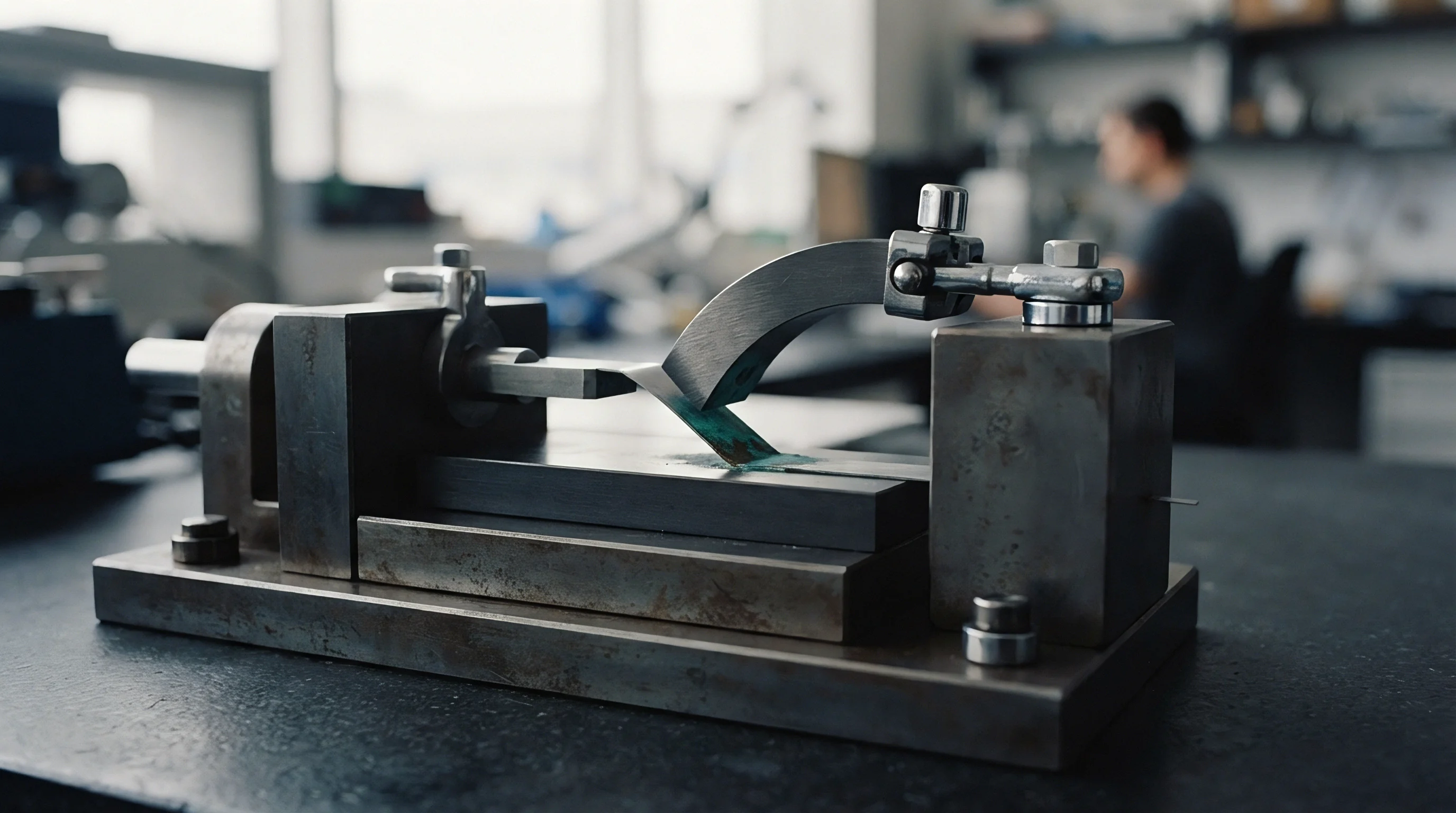

Steel
Chemical composition of mold base plates and cavity inserts dictates tool longevity, cycle speed, and dimensional integrity across multi-cavity layouts. Inexpensive plastic prototypes function inside soft aluminum tooling, but serial production molds running sixteen, thirty-two, or sixty-four impressions mandate pre-hardened and vacuum-degassed tool steels. Hardened metal resists abrasive resin.
Mold shops frequently swap alloys. Tooling fabricators seeking margin expansion substitute certified DIN 1.2343 ESR or AISI H13 tool steels with uncertified commercial-grade alloys that lack uniform microstructure. Uncertified steels contain microscopic slag inclusions that cause catastrophic cavity fracture under repetitive fifty-ton clamping pressures.
Metallurgical traceability requires mill test certificates authenticated by independent chemical assay before computer numerical control machining begins. Each tool plate, cavity block, and core insert requires heat-lot documentation recording carbon, chromium, molybdenum, and vanadium percentages. Vacuum heat treatment schedules demand digital furnace temperature charts verifying quench cycles and double-tempering operations.
Core inserts must attain a Rockwell hardness between 48 and 54 HRC to resist abrasive glass-filled polyamides, polycarbonates, or liquid silicone rubbers.
Core inserts machined from genuine DIN 1.2343 ESR tool steel maintain surface hardness above 52 HRC across five hundred thousand compression cycles under glass-filled resin.
Thermal sensors track cooling rates. Multi-cavity injection molds demand balanced thermal extraction across every impression to avoid differential volumetric shrinkage. Cooling water channels drilled into the cavity plates must sit within eight millimeters of the molding surfaces.
High-cavity designs benefit from vacuum-brazed beryllium-copper or AMPCO 940 alloy inserts positioned near deep core ribs where drilled water lines cannot reach. Substandard toolmakers omit these expensive copper-alloy cores, causing distal cavities to overheat during rapid cycling. The resulting thermal gradients warp plastic components, driving parts outside drawing tolerances during twenty-four-hour production runs.

Metallurgical Certification and Core Hardness Benchmarks
Receiving inspection of multi-cavity tooling components requires direct destructive or non-destructive physical hardness testing before tool assembly. Portable rebound hardness testers verifying Leeb scales provide initial surface checks, while laboratory Rockwell C indentation testing confirms core hardness depth. Surface nitriding or physical vapor deposition coatings, including titanium aluminum nitride, provide secondary abrasion resistance across slide faces and lifters, but surface treatments cannot compensate for inadequate base steel hardness.
Tooling documentation must incorporate complete optical emission spectrometry readouts confirming alloy compliance. Table 1 identifies the metallurgical acceptance benchmarks and hardness standards governing multi-cavity injection molds designed for serial manufacturing operations.
| Component Role | Standard Material Grade | Target Hardness (HRC) | Inspection Standard | Rejection Threshold |
|---|---|---|---|---|
| Cavity Insert | DIN 1.2343 ESR / AISI H13 | 50 to 52 | ASTM E18 Rockwell | Below 48 HRC or non-ESR purity |
| Core Insert | DIN 1.2083 / AISI 420 Stainless | 48 to 50 | ASTM E18 Rockwell | Below 46 HRC or inclusions present |
| Mold Base Plates | DIN 1.2311 / AISI P20 | 28 to 32 | ASTM E10 Brinell | Below 26 HRC or plate thickness taper |
| Slide Faces and Lifters | DIN 1.2767 / AISI 6F7 | 54 to 56 | ASTM E18 Rockwell | Below 52 HRC or unground surfaces |
| Ejector Pins | DIN 1.8550 Nitrided | 65 to 70 Surface | ISO 6507 Vickers | Core below 35 HRC or nitriding flake |
| Values reflect vacuum-quenched, double-tempered conditions verified by third-party metallurgical assays prior to final assembly. | ||||
Runner Balance and Hot Manifold Thermal Isolation
Even resin delivery across multi-cavity architectures requires precise hydraulic and thermal balancing within the runner network. Naturally balanced runner geometries feature identical flow lengths, runner diameters, and gate dimensions from the central sprue to every discrete impression. Unbalanced runners starve distal impressions.
Toolmakers seeking to minimize mold base dimensions often implement artificial runner layouts, throttling runner diameters to force plastic toward distant cavities. Artificial runner balancing produces inconsistent fill pressures, packing densities, and molecular orientation across the mold.
Hot runner manifolds mandate separate proportional-integral-derivative thermal control zones for each individual drop. Cold slugs block narrow orifices. An eight-cavity mold requires a minimum of eight independent thermal control zones, while a sixteen-cavity hot-to-cold runner configuration mandates zoned manifold heater bands and thermocouple placement adjacent to each tip.
Ceramic insulation boards measuring a minimum of ten millimeters thickness must isolate the hot runner manifold from the mold clamping plates to prevent parasitic heat loss into the machine platens. Failure to isolate the hot manifold causes thermal drift that destabilizes cavity fill balance across twenty-four-hour continuous runs.
- Core Galling Failures occur when slide angles lack adequate clearance angles, destroying sliding shutoff surfaces during initial dry cycling.
- Thermal Creep Deformations emerge when mold base backing plates lack sufficient clamping support pillars, causing center platen deflection under clamp tonnage.
- Gate Erosion Pitting develops when unhardened gate inserts face high injection velocities from glass-filled resins, enlarging gate diameters unevenly.
- Cooling Line Blockages arise from untreated fabrication fluids causing corrosion inside internal baffles, creating fifty-degree temperature differentials between cavities.
Moldmakers confronted with uneven cavity wear frequently insist that minor hardness variances fall within acceptable commercial ranges for pre-hardened billet stock.

Gauge
Acceptance protocols for multi-cavity injection molds depend upon rigorous metrological verification across every discrete impression. Inspecting five sample parts from a single designated cavity confirms tooling geometry for that specific steel pocket while concealing systemic tooling flaws across the mold block. Process drift compounds across cavities.
A sixteen-cavity tool produces sixteen distinct part geometries, each dictated by microscopic variations in computer numerical control milling paths, electrical discharge machining electrode wear, polishing depths, and local thermal conditions.
Dimensional qualification standards mandate coordinate measuring machine inspection routines executing identical measurement programs across parts harvested from all cavities during a single stabilized shot. Critical-to-quality dimensions, including sealing lips, snap-fit hooks, bearing bores, and pin clearances, must satisfy strict statistical dispersion metrics. Optical comparators measure gate wear.
Tool acceptance standards reject molds whenever dimensional variance between cavities exceeds twenty-five percent of the total engineering tolerance band established on the product definition drawing.
Acceptance agreements incorporating ISO 20457 grade DIN 16742 TG4 tolerances void final disbursement whenever cavity variance exceeds ten micrometers across sixteen impressions.
Statistical process metrics quantify tooling stability across multi-cavity layouts. Molds must demonstrate process centering metrics, designated as Cpk values, exceeding 1.67 for critical safety interfaces and 1.33 for general assembly dimensions during a continuous qualification run. Calculating a single aggregate Cpk across parts mixed indiscriminately from all cavities constitutes a metrological error.
Individual Cpk values must be calculated separately for each discrete cavity number. If cavity three yields a Cpk of 1.72 while cavity twelve yields a Cpk of 1.05, the mold fails acceptance, requiring the toolmaker to adjust local steel dimensions or balance gate geometries.

Should Cavity Centering Decouple across Tool Blocks?
Decoupling cavity-specific dimensions from overall tool block metrics reveals severe fabrication errors disguised by aggregated lot statistics. Injection molding tools featuring modular insert pockets often suffer from positional stack-up errors across the master plate. When cavity blocks are bolted into oversized pockets, clamping forces shift individual cavities out of alignment with their respective core pins.
Measuring true position tolerances relative to functional part datums exposes these hidden structural shifts.
Table 2 illustrates multi-cavity dimensional dispersion across a sixteen-cavity tool running an engineering polymer housing with a nominal critical width of 42.000 millimeters and an allowable tolerance of plus or minus 0.050 millimeters.
| Cavity Position | Measured Mean (mm) | Standard Deviation | Calculated Cpk | Acceptance Decision |
|---|---|---|---|---|
| Cavity 01 (Near Sprue) | 42.008 | 0.007 | 2.00 | Approved |
| Cavity 04 (Near Sprue) | 42.012 | 0.008 | 1.58 | Approved |
| Cavity 08 (Distal Outer) | 42.034 | 0.011 | 0.48 | Rejected: Flow Starvation |
| Cavity 12 (Distal Outer) | 42.039 | 0.012 | 0.31 | Rejected: Low Pack Pressure |
| Cavity 16 (Far Corner) | 41.968 | 0.014 | 0.76 | Rejected: Thermal Hotspot |
Statistical Dispersion Limits under DIN Sixteen Seven Four Two
International standard DIN 16742, superseding DIN 16901, establishes tolerance groups for injection-molded plastics based on material shrinkage characteristics and tool manufacturing accuracy. For precision components molded from amorphous polymers, tolerance group TG4 represents the standard industrial target for high-precision injection tooling. Molds producing semicrystalline resins like polyoxymethylene or polyphenylene sulfide fall under tolerance group TG6 due to higher volumetric shrinkage dynamics during crystallization.
Acceptance protocols must formally bind the toolmaker to specific tolerance groups defined within DIN 16742 or ISO 20457. Unincorporated buyers frequently sign generic quotations guaranteeing good workmanship without citing binding metrological standards. When the delivered tool produces parts with wall thicknesses varying by 0.15 millimeters across sixteen cavities, the vendor claims the variation reflects normal resin shrinkage.
Dimensional drift breaks automated assembly. Citing exact DIN 16742 tolerance groups within the initial tooling purchase agreement legally binds the builder to modify cavity inserts at their own expense until every impression satisfies the geometric specification.
Tolerancing errors across multiple cavities produce structural misalignment in mating subassemblies, driving scrap rates upward during high-speed production runs and triggering catastrophic warranty claims from field assemblies.
Run
Physical proving trials transform theoretical mold designs into qualified industrial production hardware. Qualification protocols divide into sequential stages designated as T0, T1, and continuous stability verification runs. The T0 trial constitutes the initial physical injection of molten resin into the tool block at the toolmaker’s facility.
T0 trials verify basic mechanical functioning, including hydraulic core pull sequences, mechanical slide timings, ejector return pin clearances, and electrical limit switch responses. Parts produced during T0 trials carry gross cosmetic and dimensional imperfections because runner balances, gate freezes, and cooling loops remain uncalibrated.
Advancing from T0 to T1 demands systematic scientific molding analysis rather than arbitrary machine adjustments. Process technicians construct viscosity curves by varying injection speeds across short shots to identify the laminar flow region of the resin. Once the optimal injection velocity is established, the technician performs gate freeze studies by measuring individual part weights across increasing pack times.
The gate freeze point identifies the exact packing duration required to seal the gate, preventing molten plastic from backflowing into the runner manifold during screw recovery.
Cavities that fill first freeze last and yield denser parts with irregular shrinkage profiles.
Short shots isolate hydraulic drag. Factory Acceptance Testing, designated as FAT, takes place on the toolmaker’s floor before signing authorization to pack and crate the mold for shipment. FAT mandates executing a minimum continuous production run of three hundred consecutive shots without operator intervention, part hang-ups, flashing, or cooling fluid leaks.
The press cycle time must match or beat the quotation benchmark. If the sales contract promised a twenty-second cycle time, a tool requiring twenty-eight seconds to eject rigid parts without distortion fails acceptance, destroying projected manufacturing unit economics.
How Does Short Shot Profiling Isolate Runner Imbalance?
Systematic short shot analysis isolates hydrodynamic resistance throughout the runner branches without the confounding influence of hold pressure. The molding technician disables the pack and hold phases on the press, dialing back the injection stroke to fill only fifty percent of total cavity volume. The press injects plastic at production velocities, freezing the advancing melt fronts mid-stride.
Visual and gravimetric evaluation of the resulting partial components exposes volumetric fill imbalances between cavities. In a sixteen-cavity mold, all sixteen frozen plastic skulls must exhibit identical visual fill patterns and component weights within a three percent margin of variation. If the four cavities closest to the main sprue fill seventy percent while the four peripheral cavities fill only twenty percent, the runner system suffers from hydraulic imbalance.
Fast cycle speeds cause flash. The toolmaker must disassemble the mold and enlarge downstream runner diameters or rebalance gate lands before attempting full part packing trials.
Continuous Cycle Proving and Ejection Stability
Reliable serial manufacturing demands mechanical durability during extended high-speed cycling. Molds running automatic production drop parts directly onto conveyors or into robotic end-of-arm tooling without human oversight. Ejection pins leave witness marks.
Misaligned ejector plates or inadequate draft angles cause parts to stick in the cavity half, triggering mold closure crashes that destroy expensive shutoff faces.
Factory Acceptance Testing mandates rigorous verification of mechanical ejection forces and clearance checks under stabilized operating temperatures. Technicians execute the following sequential verification sequence during the final acceptance trial:
- Pre-heat mold to steady-state operational temperature using production water temperature control units, checking platen surface temperatures with calibrated infrared contact probes.
- Execute fifty continuous dry cycles without resin injection at maximum press clamp speeds, monitoring hydraulic pressure spikes and verifying optical safety light curtain interlocks.
- Inject twenty consecutive shots under production process parameters, capturing full shots on clean inspection tables without touching cosmetic A-surfaces.
- Measure ejection pin breakout forces utilizing hydraulic pressure transducers, verifying that demolding forces do not exceed calculated design parameters.
- Execute a three-hundred-cycle automatic run, documenting mold parting line temperatures, hot runner tip wattages, and cycle time repeatability.
- Inspect parting line shutoffs, leader pin bushings, and slide wear plates under high-intensity ultraviolet illumination to detect metal-on-metal galling or lubrication leaks.
Balanced flow channels yield uniform part density while irregular fill patterns create localized internal stress.
Custody
Physical possession and legal title must merge cleanly into the newly registered corporate entity once certificate of incorporation arrives from company house or state registries. Promoters who executed initial machine shop purchase orders in their personal names must formally assign all contractual rights, warranties, and title to the corporate body. Late novation forfeits tax credits.
Failure to execute a written intellectual property and asset novation agreement leaves the physical mold in promoter ownership, preventing the corporation from capitalizing tooling expenditures on its balance sheet or depreciating the asset for tax purposes.
Cross-border asset assignment requires comprehensive documentation for customs and corporate compliance. The novation package must include the original purchase agreement, all verified change orders, factory acceptance test sign-offs, and an explicit transfer instrument signed by both the individual promoter and the authorized corporate officer. Customs filings demand clear ownership.
Shipping multi-cavity tooling across international borders under Harmonized System Code 8480.71 requires accurate commercial invoicing matching the corporate entity listed on import licenses, avoiding severe customs delays, impoundment, or anti-dumping penalties at entry ports.
Table 3 outlines the legal mechanics, required instruments, and operational consequences governing the transition of pre-incorporation tooling assets into a formal corporate entity.
| Formation Phase | Governing Legal Instrument | Title Holder | Commercial Risk Allocation | Accounting Treatment |
|---|---|---|---|---|
| Pre-Filing Initiation | Interim Promoters Agreement | Individual Promoters | Joint and several personal promoter liability | Personal capital advance |
| Machining Execution | Escrow Retainage Contract | Escrow Agent / Builder Lien | Artisan lien held by machining vendor | Uncapitalized deposit |
| Entity Registration | Board Ratification Resolution | Corporate Body in Formation | Corporate assumption of ongoing obligations | Paid-in capital credit |
| Final Acceptance | Asset Novation Agreement | Formal Corporate Entity | Complete release of personal promoter claims | Fixed asset balance sheet capitalization |
Asset Novation and Paid in Capital Conversion
Capitalizing pre-incorporation tooling expenses into founder equity demands board-approved valuation schedules. Promoters who personally paid fifty thousand dollars in fabrication deposits cannot simply withdraw equivalent corporate cash without creating taxable events or mischaracterizing seed investment funds. The corporate board of directors must pass formal written resolutions approving the novation agreement, converting verified out-of-pocket tooling disbursements into formal paid-in capital, common stock issuances, or formal corporate promissory notes.
Independent accounting audits require comprehensive receipt documentation connecting each payment wire to specific mold build milestones. Cancelled personal checks, foreign exchange conversion statements, and toolmaker receipt acknowledgments must accompany the corporate ledger entry. Neglecting to formalize this financial conversion triggers severe accounting audits during subsequent venture capital financings, as institutional investors demand unclouded corporate title to all production tooling and proprietary mold designs.

Bailee Risk and Physical Mold Relocation Rights
Tooling retained at third-party contract manufacturing facilities operates under legal bailment principles. The corporate buyer owns the physical asset, while the contract molder maintains custody solely for manufacturing agreed-upon part volumes. Mold storage arrangements frequently deteriorate when startups dispute piece-part pricing, minimum order quantities, or shipment yields with their contract molder.
Contract molders often refuse to release injection molds, asserting common law possessory liens over tooling blocks based on disputed inventory carrying costs or unamortized equipment setups.
Robust bailment agreements separate piece-part manufacturing purchase orders from tooling custody covenants. The agreement must explicitly declare that the molder acts solely as a bailee without proprietary rights or liens over the mold, granting the corporate owner unhindered physical access to inspect, crate, and remove the tooling upon twenty-four hours written notice. Affixing permanent, riveted stainless steel asset tags directly to the mold base plates identifies the corporate entity as the sole legal owner, preventing the molder’s creditors from seizing the tooling block during contract manufacturer insolvency proceedings.
Cross-border tax authorities continue to dispute whether pre-registration tooling development expenditure qualifies as a capital contribution or remains an unassigned personal loan when the underlying asset stays physically anchored in an offshore moulding plant.