Resolving Coordinate Discrepancies between on Machine Probing and off Line Metrology under Clamping Stress
Reconciling coordinate drift between machine probes and off-line CMMs demands kinematic fixturing, strain compensation matrices, and restrained state drawings.
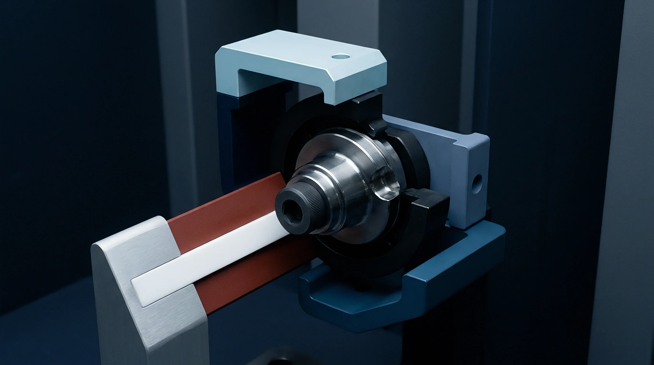
Datum
Precision machining operations rely on accurate spatial measurement to verify workpiece geometry prior to tool path execution. On-machine probing systems measure features while the component remains securely locked inside machine tool fixtures under hydraulic or mechanical clamping loads. Off-line coordinate measuring machines evaluate the identical component in a climate-controlled inspection laboratory after fixture pressure is fully released.
Discrepancies between these two measurement environments generate scrap, delay facility qualifications, and fuel commercial disputes between precision subcontractors and primary contracting partners.
Hydraulic pressure generates elastic structural strain. Workpiece material beneath clamp contact pads compresses locally while thin-walled webbing flexes across unsupported spans. On-machine touch probes register feature locations relative to the active machine tool origin while this internal stress field holds the part in a distorted state.
Unclamping releases localized workpiece distortion immediately. Upon removal from the machining fixture, stored strain energy dissipates and the component rebounds toward its unconstrained equilibrium shape. Features probed on the machine shift relative to primary datum planes, creating measured coordinate deviations between machine tool routines and quality laboratory reports.
Mechanical Deformation and Reference Frame Realignment
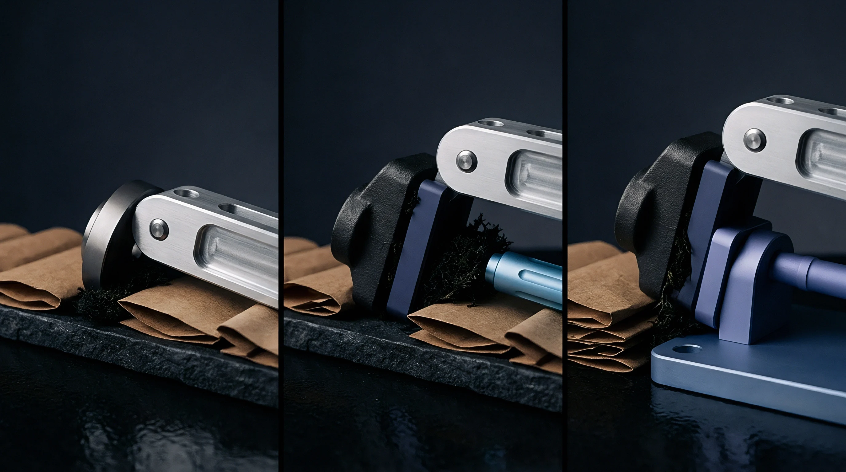
Hydraulic vices and modular fixtures apply substantial clamping loads to hold raw stock against cutting forces. These forces induce elastic strain tensors throughout the workpiece volume according to the elastic modulus and Poisson ratio of the alloy. Touch probes mounted in the machine spindle touch workpiece surfaces that have shifted from their nominal un-clamped positions.
The probe software records coordinates based on the machine axis encoders, embedding the physical clamp deformation into the measured feature position.
Off-line inspection occurs in unconstrained equilibrium. When the quality inspector places the unclamped part on granite support blocks inside the measuring room, the component occupies its true free state geometry. Coordinate measuring machine styli probe the relaxed surface, revealing spatial deviations from the on-machine dataset.
The table below lists primary deformation mechanisms responsible for coordinate mismatches across common manufacturing materials.
- Hydraulic pressure saturation causing unwanted structural bow and torsional warping in thin-walled aerospace structural elements during roughing operations
- Asymmetric clamp force distribution shifting primary locating pins away from nominal centerline alignments prior to spindle touch probing
- Frictional resistance at resting pads locking severe residual machining stress into workpiece bulk until fixture release allows thermal relaxation
- Thermal gradient accumulation compounding mechanical clamping strain during extended multi-axis milling sequences without adequate coolant soak time
Clamping forces applied directly over solid datum supports prevent bending moments during probe cycles.
Free State Measurement against Restrained Specifications
Engineering drawings designated under international drafting standards distinguish between unconstrained components and assemblies measured under simulated installation forces. Standards such as ISO 10579 and ASME Y14.5 supply explicit annotations for flexible parts, authorizing specific clamping pressures during off-line inspection when parts deform under gravity or residual stress. When engineering drawings lack flexible part annotations, off-line inspection standards dictate unconstrained free state measurement.
Standard touch probes register surface contact. Without explicit restrained condition callouts on technical drawings, quality control teams reject components whose free state dimensions fail blueprint tolerances, even when on-machine probing confirmed perfect geometry under fixture restraint. Resolving this misalignment requires engineering teams to quantify clamp deflection vectors and apply reverse compensation matrices directly to machine tool coordinate systems.
Friction coefficients between steel fixture jaws and raw aluminum stock vary between 0.15 and 0.45 depending on coolant oil film thickness, making exact clamping friction unpredictable without serrated mechanical locators. Machining facilities overcome this friction uncertainty by installing hard contact pins that fix contact geometry regardless of fluid lubrication.
Failing to reconcile fixture deformation before volume production causes batch rejections during initial article inspection, forcing expensive rework cycles and wasting machining capacity.

Strain
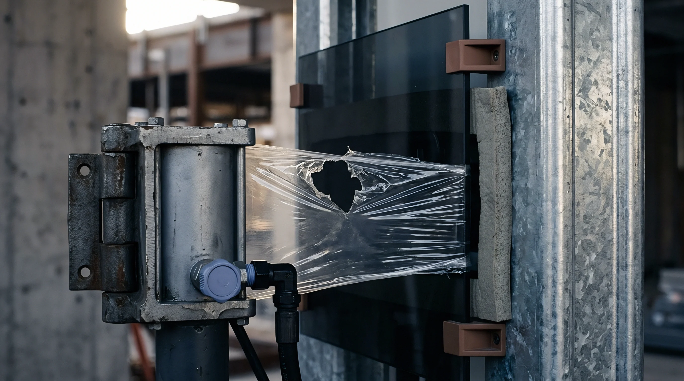
Component deflection under fixture loading generates localized stress distributions that alter feature positions during cutting operations. On-machine touch probes touch surfaces displaced by mechanical clamping, recording coordinates that reflect both tool path motion and elastic distortion. Quantifying this strain requires evaluating the workpiece material properties alongside fixture geometry and applied clamping force vectors.
Spatial coordinates shift along three axes. When a three-jaw chuck or hydraulic vise exerts clamping force, localized material compression propagates through the part body. The magnitude of feature movement depends directly on material stiffness, wall thickness, and distance from clamping contact points.

Elastic Recovery and Vector Transformation Matrices
Unclamping raw titanium or high-strength aluminum stock releases stored potential energy, causing workpiece surfaces to spring back toward initial equilibrium. Elastic modulus dictates strain recovery magnitude. High-modulus materials like stainless steel experience smaller spatial displacement under equivalent clamp force compared to low-modulus aluminum or titanium alloys.
Standard probe calibration uses granite reference spheres to set stylus tip radius compensation values under static conditions. Stylus tip deflection calibration values of 1.2 micrometers rest on Renishaw OMP60 artifacts evaluated at 20 degrees Celsius across 50 probing passes. Dynamic fixture strain during production machining distorts this baseline calibration, shifting touch probe contact coordinates relative to the machine axis encoders.
Mathematical transformation matrices convert on-machine touch coordinates into relaxed state estimations using linear elasticity calculations.
| Material Grade | Elastic Modulus (GPa) | Clamp Pressure (kN) | Calculated Strain (μm) | Post-Release Shift (μm) |
|---|---|---|---|---|
| Aluminum 7075-T6 | 71.0 | 14.0 | 72.4 | 68.1 |
| Titanium Ti-6Al-4V | 114.0 | 14.0 | 45.1 | 41.8 |
| Stainless Steel 316L | 193.0 | 14.0 | 26.6 | 24.2 |
| Inconel 718 | 205.0 | 14.0 | 25.1 | 22.9 |
Finite Element Approximations for Probe Vector Offsets
Predictive software models discretize complex aerospace geometries into localized solid meshes to simulate force application across fixture contact pads. These simulations generate three-dimensional displacement fields that map feature deflection under specific clamp loads. Programmers export these calculated deflection vectors directly into machine control post-processors, dynamically shifting tool paths and touch probe routines to offset physical part deformation.
Aluminum alloys flex under moderate forces. Machine operators without access to finite element predictive software rely on practical empirical probe sequences to measure clamping strain directly on the shop floor.
- Record baseline coordinate locations using on-machine probing while hydraulic fixture holds workpiece under nominal clamping pressure.
- Execute roughing and finishing machining operations to generate final feature geometry within machine tool envelope.
- Re-probe critical feature centroids under active clamp pressure to document internal machine reference coordinates.
- Release hydraulic pressure completely, allowing workpiece elastic strain to recover into unconstrained equilibrium state.
- Re-engage clamps at minimal seating pressure and re-probe feature centroids to isolate pure clamping deflection vectors.
Touch probe compensation vectors calculated under active clamp load fail to predict coordinate drift once hydraulic pressure releases.
Subcontract machining suppliers often claim that on-machine probes confirm component accuracy, arguing that off-line laboratory inspection tools introduce environmental measurement errors during post-process audits.
Protocol
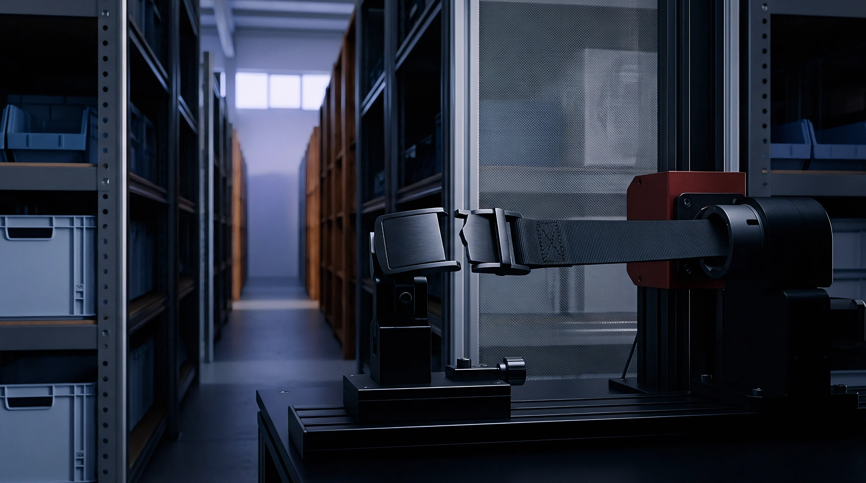
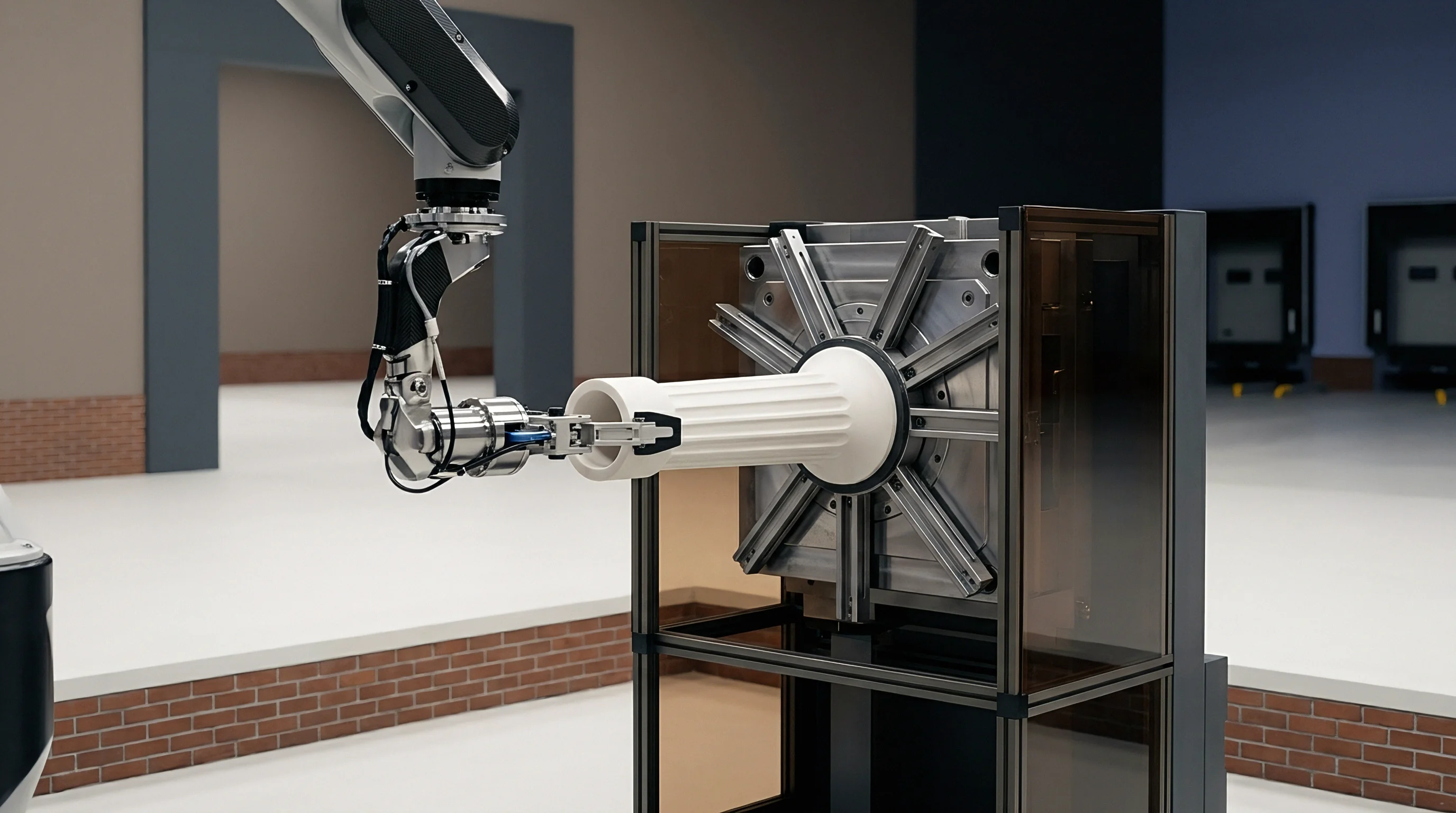
Standardized inspection workflows establish guidelines for aligning machine tool touch systems with laboratory coordinate devices. Eliminating measurement discrepancies requires strict alignment between physical fixturing hardware, probing subroutines, and thermal control procedures across manufacturing environments. Establishing identical coordinate reference frames ensures that feature positions recorded on the machine tool match off-line CMM records within defined uncertainty bounds.
Matrix algebra corrects touch probe vectors. Machine tool touch probes require routine calibration against reference artifacts traceable to international metrology standards. Implementing kinematic mounting fixtures prevents unwanted part strain by isolating clamping force paths from critical datum faces.
Kinematic Support Design and Multi-Point Touch Routines
Exact-constraint fixturing methods replace planar surface clamps with ball-ended contact points to reduce unwanted structural bending. Kinematic 3-2-1 locating structures constrain six degrees of spatial freedom without introducing redundant mechanical forces. Spherical locators eliminate redundant clamping constraints.
By applying clamping force directly opposite hardened support points, kinematic mounts prevent bending moments from distorting thin-walled component geometry during both machining cycles and probing routines.
Precision grinding of silicon wafer steppes in semiconductor fabrication facilities faces similar nanometer-scale clamping distortion, where electrostatic chucks replace hydraulic jaws to limit substrate warping. Sub-contract machining operations operate under identical mechanical principles at larger millimeter scales.
Multi-point probing algorithms calculate feature centroids by averaging multiple touch points across circular and planar features. Increasing touch point density reduces localized surface roughness errors and minimizes stylus force deflection impact on coordinate calculations.
- Kinematic locating pin engagement preventing over-constraint while maintaining repeatable origin transfer within two micrometers across shifting setups
- Torque-controlled manual clamp tightening eliminating operator variability during preliminary datum setting prior to automated touch routines
- In-process probe calibration against ceramic artifact updating stylus tip radius compensation values prior to critical feature measurement passes
- Dual-environment temperature tracking logging shop floor ambient fluctuations against climate-controlled laboratory baselines continuously
Adherence to ISO 10360-2 calibration routines forces on-machine touch probes to match coordinate measuring machine accuracy boundaries within specified uncertainty budgets.
Cross Calibration Standards across CNC and CMM Workspaces
Traceability between machine tools and dedicated inspection rooms requires identical artifacts evaluated under standardized temperature settings. ISO 230-2 defines test procedures for evaluating machine tool axis repeatability, while ISO 10360-2 governs coordinate measuring machine volumetric accuracy. Establishing cross-calibration protocol requires probing a master artifact on the machine tool, transferring the artifact to the CMM, and comparing coordinate datasets to derive zero-point offset vectors.
Thermal ambient shifts alter machine zero. Shop floor temperature variations expand machine ball screws and workpiece castings, compounding mechanical clamping errors during probing cycles. Dual-axis temperature sensors feed thermal compensation algorithms inside the machine controller, adjusting coordinate systems before touch probes make contact with workpiece surfaces.
Section 4.2 of standard quality agreement contracts mandates that supplier manufacturing facilities perform dual-environment artifact cross-calibration every ninety operational days to maintain valid parts acceptance authority.
Arithmetic
Engineering calculations reveal the physical magnitude of positional discrepancies induced by hydraulic vise pressures acting on flexible metal plates. Validating coordinate shifts requires walking through a complete physical scenario, tracking elastic strain calculations through fixture release and off-line CMM measurement verification.
Precision manufacturing demands traceable measurement alignment. Consider a structural aerospace rib component machined from 7075-T6 aluminum plate stock. The component measures 450 millimeters in length, 180 millimeters in width, and features a uniform wall thickness of 6.0 millimeters.
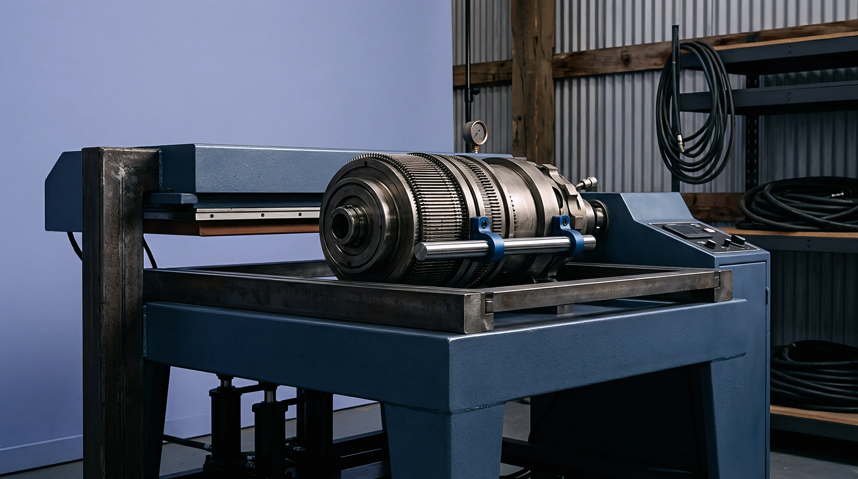
The material possesses an elastic modulus of 71 gigapascals and a Poisson ratio of 0.33. The raw plate is secured inside a four-jaw hydraulic vise fixture, where four contact pads each exert 3.5 kilonewtons of clamping force, delivering a cumulative 14.0 kilonewtons of restraining load across total pad area of 400 square millimeters.
Quantifying Elastic Deflection in Structural Aluminum Components
Consider an aerospace mounting bracket machined from solid plate stock under uniform hydraulic restraint. Clamping load creates localized compressive strain beneath the pads while generating bending deflection along the 450-millimeter unsupported span. Applying beam deflection mechanics under eccentric point loading yields a calculated vertical bending strain deflection of 0.072 millimeters along the Z-axis, accompanied by a lateral Poisson expansion of 0.038 millimeters across X and Y coordinate axes.
During machining, a precision bore centroid is finished at nominal location X = 125.000 millimeters, Y = 80.000 millimeters, Z = 15.000 millimeters. Immediately following tool path execution, an on-machine touch probe contacts the bore circumference under active hydraulic clamping load. The probe system registers the strained hole center location at X = 125.045 millimeters, Y = 80.012 millimeters, Z = 15.000 millimeters.
Unclamping releases localized workpiece distortion immediately. Stored potential energy dissipates completely upon fixture release. The component undergoes elastic strain recovery, springing back toward its relaxed equilibrium state.
Vertical strain recovery restores 0.068 millimeters of Z-axis surface distortion, while lateral springback shifts horizontal coordinates by 0.031 millimeters. Discrepancy values exceed drawing tolerance bands.
Reducing vise clamping force from 3.5 kilonewtons to 1.2 kilonewtons lowers post-release spatial coordinate shift in 7075-T6 aluminum from 74.7 micrometers to 14.0 micrometers.
Calculating Coordinate Offsets and Residual Stress Drift
Translating touch probe data into post-release dimensional predictions involves systematic mechanical transformation formulas. The off-line coordinate measuring machine evaluates the unclamped component inside a climate-controlled laboratory at 20 degrees Celsius. The inspection probe measures the unconstrained bore centroid at X = 125.014 millimeters, Y = 80.010 millimeters, Z = 15.068 millimeters.
Calculating total spatial discrepancy magnitude between on-machine probing data and off-line CMM inspection data utilizes 3D Euclidean distance formulation:
Delta X = 125.045 – 125.014 = 0.031 millimeters
Delta Y = 80.012 – 80.010 = 0.002 millimeters
Delta Z = 15.000 – 15.068 = -0.068 millimeters
Discrepancy Magnitude = Square Root of ( (0.031)^2 + (0.002)^2 + (-0.068)^2 )
Discrepancy Magnitude = Square Root of ( 0.000961 + 0.000004 + 0.004624 )
Discrepancy Magnitude = Square Root of ( 0.005589 ) = 0.0747 millimeters (74.7 micrometers)
The calculated discrepancy rests on 7075-T6 Young’s modulus of 71 gigapascals evaluated across a 10-specimen tensile batch test. Shift parameters move if alloy heat treatment varies yield strength or grain orientation across mill shipments.
This 74.7 micrometer spatial shift exceeds a standard aerospace hole location tolerance of 0.050 millimeters, causing off-line inspection failure despite passing on-machine probe checks. Re-calculating fixture setup with hydraulic clamping force restricted to 1.2 kilonewtons per pad reduces elastic deflection to 0.013 millimeters vertical and 0.005 millimeters horizontal. Post-release spatial discrepancy drops to 0.014 millimeters (14.0 micrometers), bringing the finished part safely within specified engineering blueprint boundaries.
Fixture clamping forces balanced precisely over rigid datum points eliminate elastic springback across thin-walled plate structures.
Contract
Legal supply agreements governing precision manufacturing establish clear procedural rules for arbitrating dimensional discrepancies between machining centers and quality control laboratories. When off-line inspection rejects components that passed on-machine probing, operational friction threatens production schedules, capital expenditure releases, and joint venture partnerships. Structuring unambiguous quality acceptance agreements protects contracting parties from unallocated scrap costs and facility qualification delays.
Suppliers absorb non-conforming scrap expenses. Technical contracts must specify which measurement environment serves as the legally binding authority for final product acceptance. Defining explicit metrology protocols inside manufacturing supply agreements prevents costly legal arbitration over rejected precision component batches.
Quality Agreement Clauses and Metrology Verification Gates
Precision component purchase orders specify binding acceptance parameters for parts evaluated in both constrained and relaxed states. Quality contracts define gauge repeatability and reproducibility (GR&R) thresholds, mandating that all inspection equipment demonstrate less than 10 percent total measurement variation. Machine tool touch probes must undergo certified cross-calibration against laboratory CMMs before on-machine measurement data can support product acceptance release.
Quality contracts dictate legal acceptance limits. The table below outlines formal qualification milestone gates required inside manufacturing joint venture contracts to manage metrology alignment and scrap liabilities.
| Milestone Gate | Metrology Reconciliation Standard | Retention Release (%) | Failure Consequence Allocation |
|---|---|---|---|
| Gate 1: Fixture Validation | Kinematic clamp deflection < 10 μm | 20.0 | Supplier refabricates fixture tooling |
| Gate 2: Probe Cross-Calibration | CNC-CMM artifact correlation < 5 μm | 30.0 | Shared recalibration diagnostic costs |
| Gate 3: First Article Inspection | Restrained vs free state offset < 15 μm | 30.0 | Subcontractor absorbs scrap and delays |
| Gate 4: Production Run Approval | Batch Cpk > 1.67 in free state inspection | 20.0 | Full warranty liability on batch rejection |
| Note: Acceptance gates governed by AS9100 quality system requirements and ISO 10360 inspection compliance. | |||
Scrap Allocation and Capital Expenditure Risk Allocation
Financial losses resulting from rejected production batches create immediate operational tension between machining vendors and prime contractors. Contracts lacking clear metrology arbitration clauses force suppliers to absorb raw material and machining operational burn costs when off-line CMMs reject parts passed by on-machine probes. Incorporating flexible part drawing designations per ISO 10579 protects vendors from improper unconstrained inspection rejections on flexible aerospace structures.
Retained earnings absorb process scrap. Prime contractors safeguard capital expenditure investments by tying milestone equipment payments to successful metrology reconciliation. Payment schedules release capital funds only after off-line laboratory inspection confirms that machine-probed components meet free state blueprint tolerances consistently across multi-batch production runs.
Whether future artificial intelligence closed-loop machining control systems can dynamically calculate and compensate for complex non-linear clamp strain in real time without physical kinematic fixturing adjustments remains an open operational question across precision engineering industries.