Establishing Initial Measurement Calibration and Thermal Stability Protocols for Prototype CNC Tooling Runs
Establishing CNC calibration and thermal stability requires laser kinematic mapping, spindle warm-up cycles, probe vector qualification, and CMM reconciliation.
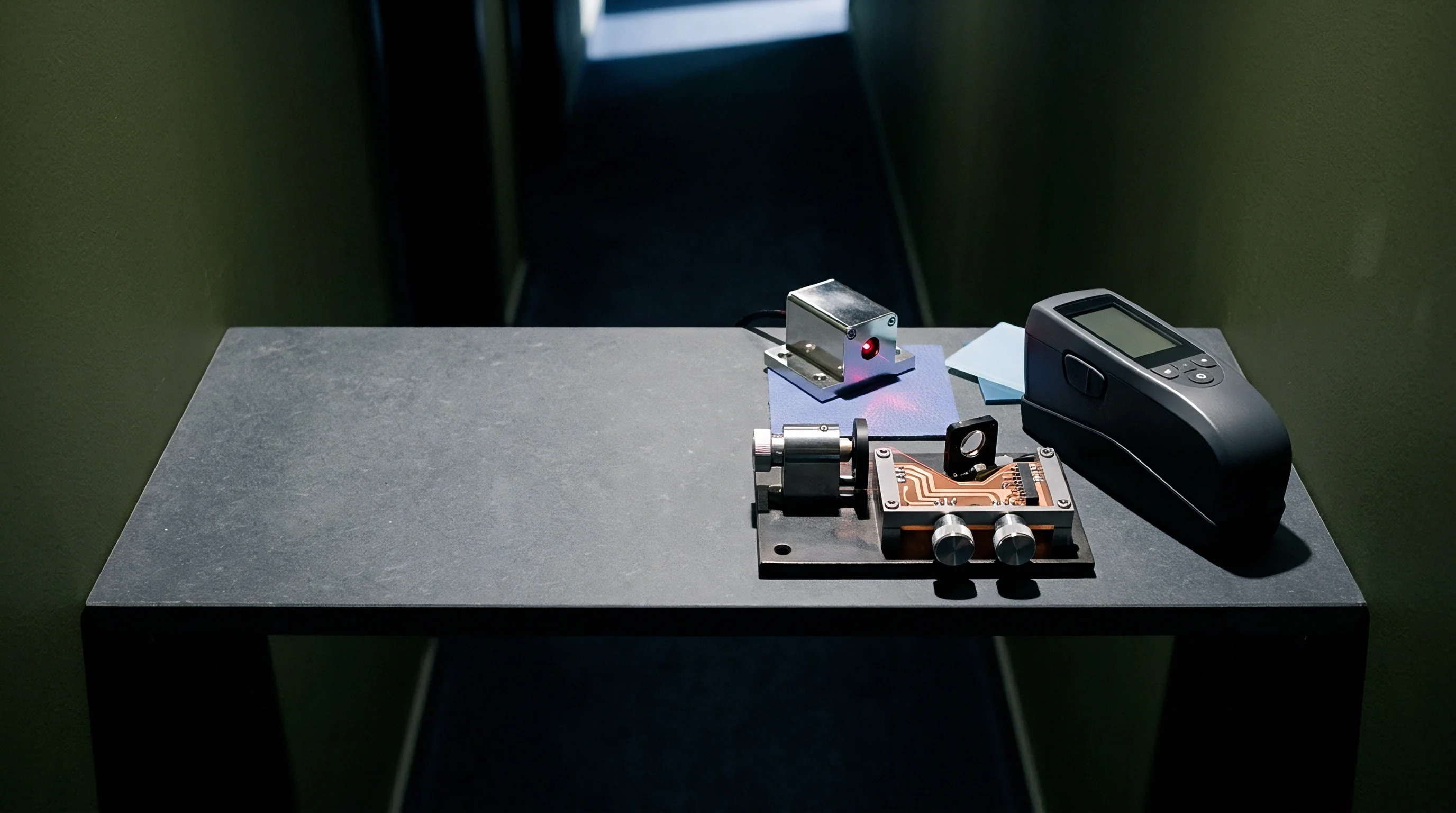

Datum
Tooling qualification in a prototype machining cell starts with geometric alignment long before raw stock meets the fixture bed. Spatial errors build up across guideways, rotary platters, and ballscrew assemblies during high-speed moves. Establishing static volumetric accuracy sets the baseline envelope that every subsequent thermal and mechanical calculation relies on, using laser interferometry for linear pitch errors and double-ballbar sweeps to catch squareness issues and dynamic backlash across multi-axis interpolations.
Machine axes show pitch, yaw, and roll deviations that shift along the travel stroke. Correcting these kinematics requires traceable artifact standards, optical collimators, and calibrated step gauges set directly on the table, tying the physical spindle taper to the machine table datums through an optical coordinate baseline.
Laser interferometer linear positioning deviation exceeds four micrometres per metre when volumetric temperature compensation operates uncalibrated across a five-degree ambient gradient.
Verifying structural alignment follows a strict sequence of diagnostic runs:
- Linear pitch verification maps lead error along individual axes with laser tracking across the full stroke, generating compensation tables for the computer numerical control registry.
- Angular squareness diagnostics identify perpendicularity errors between orthogonal travel planes using telescopic ballbar circular interpolation at standard cutting feedrates.
- Spindle center-line alignment checks concentricity between the tool holder rotational axis and the rotary table center of rotation using precision test arbors and dial test indicators.
- Dynamic volumetric mapping logs combined multi-axis positional errors across thirty-six distinct spatial coordinates to build the numerical compensation matrix for the controller core.
Skipping the mechanical baseline guarantees that later part errors get blamed on tool deflection or thermal drift, leaving operators endlessly chasing tool offsets through prototype runs.

Soak
Shop floor temperature swings warp machine castings, bridges, and drive assemblies unevenly across a shift. Setting up thermal stability protocols demands structured warm-up cycles, controlled environmental soaking, and spindle motor duty-cycle stabilization before cutting any tight tolerances.
Reaching thermal equilibrium takes hours, as spindle bearings generate localized thermal plumes that migrate into the casting well before cutting tools contact raw stock. As rotational friction heats the bearing sets, the spindle housing expands axially, pushing the tool holder nose downward into the workpiece zone.
Spindle bearings generate localized thermal plumes that migrate into the casting well before cutting tools contact raw stock.
Tracking thermal growth across individual machine elements during warm-up explains why prototype cuts made on cold iron fail tolerance:
| Subsystem Element | Heat Source | Time to Equilibrium | Peak Displacement | Stabilization Action |
|---|---|---|---|---|
| Main Spindle Housing | Bearing friction and internal stator windings | 120 to 180 minutes | 12 to 28 micrometres Z-axis growth | Continuous pre-run spindle cycling at 60 percent maximum rotational speed |
| X/Y Axis Ballscrews | Nut friction and bearing thrust blocks | 45 to 90 minutes | 8 to 15 micrometres linear expansion | Pre-machining axis exercise routines and internal coolant through-screw cooling |
| Cast Iron Machine Bed | Ambient plant air temperature shifts | 240 to 360 minutes | 15 to 35 micrometres volumetric distortion | Shop environment climate control within plus or minus one degree Celsius |
| Flood Coolant Reservoir | Fluid pump energy and chip shearing friction | 60 to 120 minutes | 5 to 12 micrometres workpiece variance | Active closed-loop refrigeration chilling set to match bed casting temperature |
A thirty-minute warm-up cycle leaves the spindle housing warm to the touch, but structural equilibrium across the casting requires hours more before cutting tight tolerances.
Probe
On-machine measurement routines rely on touch-trigger or optical workpiece probes loaded directly into the spindle taper. Vector calibration establishes the effective radius of the stylus sphere across multiple approach angles, countering stylus ball runout, shank bending compliance, and transducer switching delays that distort coordinate readings unless referenced against certified spheres.
Qualifying trigger characteristics with artifact rings at feedrates matching planned inspection cycles isolates stylus deflection from machine dynamics. A three-lobed touch mechanism triggers earlier along trip-leg directions than across intermediate sectors, requiring multi-point radial calibration routines to compensate for the directional lobing.
Compliance with ISO 230-3 testing parameters forces machine builders to document thermal distortion drifts across six continuous operating hours before prototype runoff acceptance.
Calibration accuracy depends on isolating several physical variables in the measurement loop:
- Stylus ball sphericity determines baseline roundness limits during calibration against grade 5 reference spheres.
- Transducer pre-travel variation creates directional offsets that require twenty-four point vector calibration matrices stored in probe software.
- Shank material stiffness prevents excessive mechanical deflection when employing extended ceramic or carbon fiber stylus extensions.
- Spindle orientation repeatability controls mechanical indexing consistency each time the tool changer seats the probe body into the spindle taper.
Master supply agreements for aerospace tooling define ISO 10360-5 stylus qualification records as mandatory pre-conditions for prototype first-article inspection acceptance.

Drift
Cutting forces, fluid circulation, and metal chip buildup feed heat continuously into the machine enclosure during prototype runs. As tool edges dull, the increased friction dumps thermal energy into the tool holder and raw stock, masking structural axis deflection as thermal expansion accelerates. Uneven delivery of chilled coolant compounds the problem by introducing localized thermal shock.
Should Coolant Chilling Run Continuously between Setups?
Holding tolerances means maintaining fluid temperature through both cutting passes and setup pauses. Unchilled coolant tanks climb ten to fifteen degrees Celsius over four hours of roughing, whereas circulating chilled fluid at a set temperature keeps the aluminum and steel fixture plates from expanding under prototype parts.
To catch bridge distortion from ambient temperature shifts, high-precision manufacturing cells monitor structural temperatures with surface thermistors mounted to the column, spindle headstock, and machine base.
Thermal distortions introduce systematic errors across the work volume through identifiable mechanisms:
- Asymmetric spindle carrier heating tilts the tool axis relative to the fixture table plane.
- Localized coolant pooling induces uneven thermal gradients across large aluminum workpieces, warping finished features after fixture unclamping.
- Chips packing in internal enclosures conduct residual shearing heat directly into casting ribs.
- Recirculating ballscrew heating stretches linear drive scales between fixed thrust bearings.
Cutting tool offsets stay stable only when machine structural temperatures and fluid temperatures converge, preventing rapid drift in raw cut dimensions.
Reconciliation
Final prototype qualification comes down to reconciling on-machine probing data with off-line coordinate measuring machine inspections. Dimensions recorded while clamped reflect fixture strain, coolant surface tension, and part temperature; releasing those clamps lets internal stresses relax during off-line checks, exposing geometric changes that were masked on the machine bed.
Where Do Coordinate Discrepancies Originate?
Dimensional agreement hinges on temperature equalization before off-line inspection begins. Aluminum expands twenty-three micrometres per metre for every degree Celsius of temperature rise, meaning parts moved from warm machine enclosures to a standard twenty-degree metrology room shrink measurably over their first few hours on granite.
Workpieces spend their stabilization time resting on the machine table under active coolant circulation before taking finish passes.
| Inspection Parameter | On-Machine Probing Envelope | Off-Line CMM Envelope | Correlation Tolerance | Root Cause of Spread |
|---|---|---|---|---|
| Bore Diameter (50mm to 100mm) | Plus or minus 4 micrometres | Plus or minus 1.2 micrometres | 5.0 micrometres | Stylus lobing and spindle taper runout vs scanning head accuracy |
| Hole-to-Hole True Position | Plus or minus 6 micrometres | Plus or minus 1.8 micrometres | 7.5 micrometres | Axis kinematic squareness and thermal ballscrew growth |
| Surface Flatness (300mm span) | Plus or minus 8 micrometres | Plus or minus 2.5 micrometres | 9.0 micrometres | Clamping force deformation and machine table sag under load |
| Linear Step Height | Plus or minus 5 micrometres | Plus or minus 1.5 micrometres | 6.0 micrometres | Spindle Z-axis growth and tool length preset gauge repeatability |
Between settling machine foundations and thermal workpiece expansion, establishing operational correlation limits between the machine bed and the quality control laboratory provides a defensible inspection chain for prototype tooling validation.
Whether closed-loop on-machine probing can ever fully replace off-line metrology when fixture clamping distortion outweighs volumetric machine drift remains an open question in high-speed prototype work.